- Manufacturing
Radiography Testing
Eddy Current Testing
- Distribution
Ultrasonic
Electro Magnetic
- Automation
- Support Services
- About Us
- Contact Us
The success of any Non-Destructive evaluation involving fluorescent inspection is highly dependent on the effective UV Lamp complying to the international standards and meeting the industry norms. With the advancement in technology the industry has adapted the high intensity LED UV-A light sources as go-to solution for NDT Professionals.
While safety and flexibility are one of the main advantages of LED, we also must specify more details to understand its performance for Non-Destructive Testing. To use the correct lamp for fluorescent inspection many factors in accordance with ASTM E3022 must be considered as mentioned below:
Peak Wavelength
To ensure that an LED UV-A lamp produces fluorescence in penetrants and magnetic particle materials, the LEDs must have a peak wavelength within the range 360 – 370 nm as measured with a spectroradiometer in accordance to ASTM E-1444. Wavelength is a dominating factor as lower wavelengths may emit UV-B/UV-C which cause serious health issues.
Also, greater wavelengths may emit excess of visible light forming deep violet glare. Sometimes to block visible emission (Deep violet glare) UV-A pass filter is used, particularly for inspection in Aerospace industry.

UV-A and Visible Light Intensity
In accordance with ASTM E1444/E1444M, Black Light or UV Lamps must produce a minimum acceptable intensity of 1000 μW/cm2 at 15 inch [38.1 cm] from the front of the filter to the face of the sensor. If the UV light produces more than the accepted ambient visible light, then it causes risk of missing critical indications. Ambient visible light produced by the Lamp during Fluorescent magnetic particle examinations in a darkened area can have a maximum ambient light level of 2 fc [22 lx] measured at the part surface.
Both the UV and Visible intensity shall be checked with meters that are to be calibrated every 6 Months by the manufacturer or by any Nationally accredited laboratory.
Beam Irradiance Profile Emitted by the Lamp
The UV Lamp must emit a uniform beam with the beam irradiance profile in accordance with ASTM E3022 from a distance of 15 ± 0.25 inch [38.1 cm] above the surface of a flat, level workbench with the projected beam orthogonal to the workbench surface. This is to ensure that a in a given area, the UV Light is rationally distributed so as to avoid any chance of missing critical surface defects.
| Example of Beam Irradiance Profile | Example of Uniform and Non-Uniform Projected Beams |

Blue <200 μW/cm2, Green 200-1000 μW/cm2, Yellow 1000-5000 μW/cm2, Red 5,000-10,000 μW/cm2, White > 10,000 μW/cm2
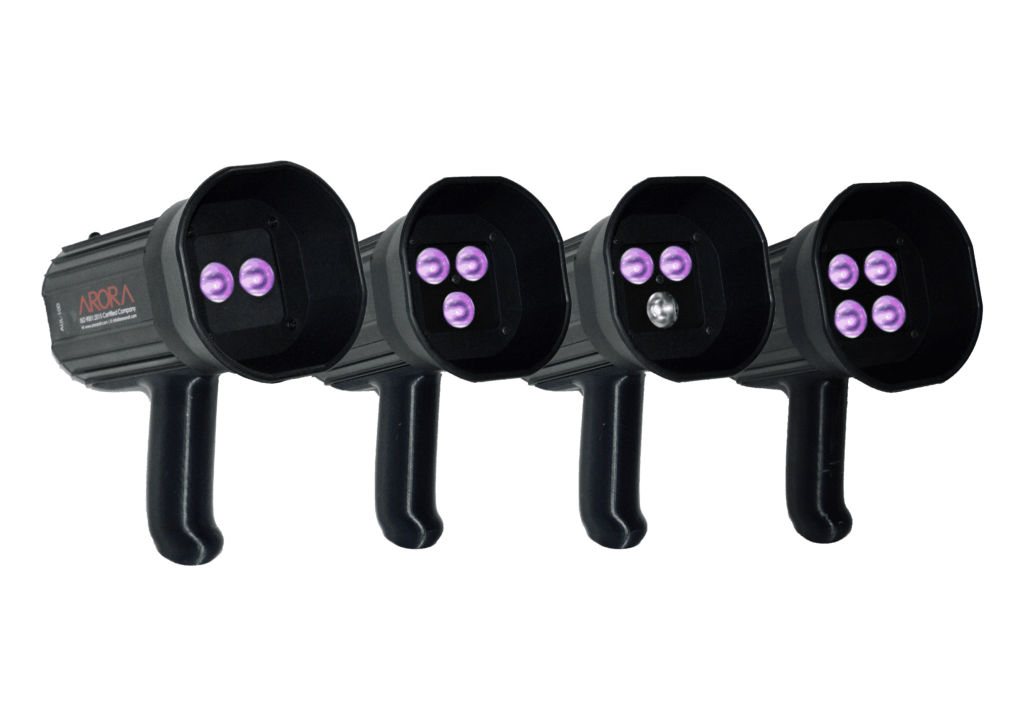
Design and Ergonomics
The design of the Lamp should be user friendly with correct positioning of power switch, charging port etc. Optimal design helps save appreciable inspection time of user. It also helps in heat dissipation and optimum focusing. Material used for manufacturing housing of lamp is also crucial as it influences weight, heating, and miscellaneous factors which further influences user friendliness of the UV Lamp.
An ISO 9001:2015 Certified Company
©2024 Arora Technologies (P) Limited, All Rights Reserved